Mastering Driveline Angles in a Custom Engine Swap
Installing a new engine in a custom swap is about much more than just making it fit. The single most overlooked—and most critical—factor for a vibration-free, long-lasting drivetrain is driveline alignment. This requires setting precise angles for the engine/transmission and the rear axle (pinion).
Contrary to what one might assume, the engine and transmission assembly is rarely perfectly horizontal. In a rear-wheel-drive (RWD) vehicle, the engine is typically mounted with the rear (tailshaft) pointing downward a few degrees.
1. Why the Angle Exists:
Drivetrain Clearance: The primary reason is to allow the transmission's bulk and the driveshaft to clear the chassis and tunnel. Slanting the assembly down pushes the tailshaft and driveshaft lower, creating room for the top of the engine and intake manifold under the hood.
Lubrication: On some transmissions, a slight downward angle helps ensure the transmission output shaft bushing and rear bearing receive proper lubrication, particularly critical during hard braking.
Center of Gravity: While minor, tilting the engine slightly helps lower the overall center of gravity, which aids handling.
2. What is Too Much or Too Little Angle?
The engine/transmission angle (often called the Transmission Slope) is your starting point. Most factory RWD setups use a downward angle of 2 to 4.
Too Little (Near 0): While tempting, a perfectly flat (or 0) engine angle can sometimes complicate driveshaft alignment or compromise clearance.
Too Much (Over 4): A steep angle will force the U-joints to operate beyond their optimal range, leading to premature wear and vibration, or may cause serious oil starvation issues in the engine or transmission.
The Critical Importance of Driveline Angles
The driveshaft and the universal joints (U-joints) are what necessitate precise angles. U-joints do not transmit speed uniformly when rotating at an angle; they speed up and slow down twice per revolution.
Why Drivetrains Need Angle (And How the Angles Must Relate)
The goal of driveline geometry is to ensure that the two U-joints—the one at the transmission and the one at the differential (pinion)—cancel out each other's speed fluctuations. This is achieved by adhering to two cardinal rules:
Equal Angles: The operating angle of the front U-joint (between the transmission output shaft and the driveshaft) must be equal to the operating angle of the rear U-joint (between the driveshaft and the pinion shaft).
Opposite Phasing: When viewed from the side, the transmission output shaft and the pinion shaft must run parallel to each other, or slightly converging/diverging in a controlled manner.
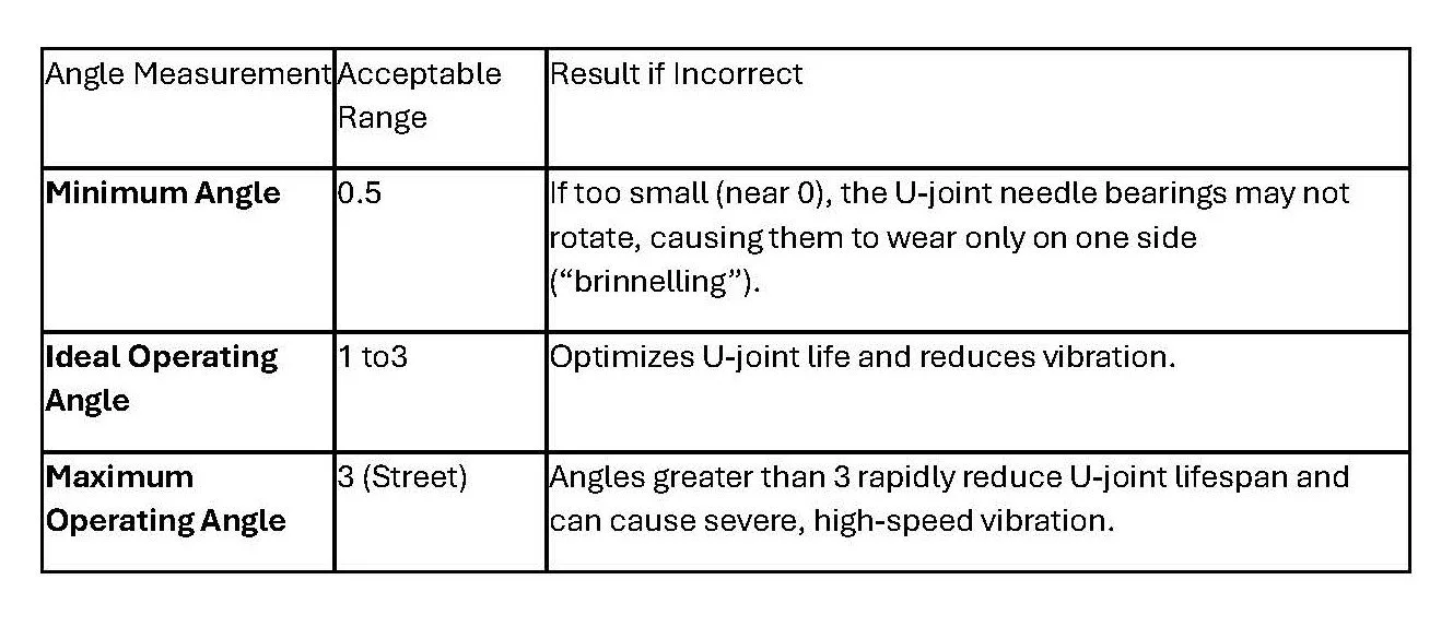
U-Joint Operating Angle Tolerances
The U-joint operating angle is the difference in degrees between the driveshaft and the component it connects to (transmission or pinion).
How to Set the Angle on a Custom Engine Swap
Setting the correct angles is the final, non-negotiable step before welding in engine and transmission mounts. The vehicle must be resting at its normal ride height and loaded weight to take accurate measurements. A digital inclinometer (angle finder) is essential for accuracy (within 0.1).
The Procedure (Conventional Two-Joint Driveline)
The goal is to set the pinion angle to be1 to 2 less than the transmission angle, accounting for pinion rotation under load.
Measure Transmission Slope:
Place the inclinometer on a flat, machined surface of the transmission (often the output flange or a machined surface on the bellhousing/pan rail).
Note the angle and direction (e.g., 3.0 Downward).
Calculate Target Pinion Slope:
Under hard acceleration, the rear axle's pinion housing will rotate upward due to torque. This movement is called pinion deflection.
To compensate, you must initially set the pinion to a greater downward angle than the transmission so that when the torque hits, it deflects into a near-parallel alignment.
Target = (Downward) - 1 to 2 of Anti-Squat/Deflection.
Example: If is 3.0 Down, your target pinion angle is 1.0 to 2.0 Upward (if you're a drag racer setting negative pinion angle) or2.0 to1.0 Down relative to the ground to establish a parallel driveline for a street car. For street cars, the most common setup is Down and Up, creating equal but opposite angles relative to the driveshaft.
Set Pinion Angle:
Using the inclinometer on the pinion yoke flange, adjust the angle of the rear axle using axle shims (leaf springs) or adjustable suspension links (4-link/ladder bar).
For a street car, aim for the two shafts to be parallel with each other, meaning the front and rear U-joint operating angles are the same (within 0.5) to achieve smooth rotation.
Failing to properly set these angles will result in harmonic vibrations, often felt at highway speed, which will quickly destroy your U-joints and lead to costly repairs.